ASTM D149-2009 dielectric breakdown voltage test method
Breakdown voltage of solid electrical insulating materials at industrial frequencies
And standard test method for insulation strength 1
This standard is issued under the fixed code D149. Subsequent figures indicate the year in which the original text was formally adopted; in the case of revisions, the last revised year number; the number in parentheses is the last reconfirmed year number. The superscript symbol (ε) indicates an edit modification to the last modified or redefined version.
This standard has been approved for adoption by the Department of Defense.
Voltage withstand breakdown tester 1. Scope
1.1 This test method covers the process of determining the dielectric strength of solid insulating materials at industrial frequencies, ie under specified specific conditions. 2,3
1.2 Unless otherwise stated, the specified frequency for this test is 60 Hz. However, this test method can also be applied to conditions of 25 to 800 Hz. If the frequency is greater than 800 Hz, then the problem of media heating will occur.
1.3 This test method will be used in conjunction with other ASTM standards or other standards related to the test method. The specific criteria used are detailed in the references to this method (see 5.5).
1.4 The method can be applied to a variety of temperatures, as well as suitable gaseous or liquid phase environmental media.
1.5 This method cannot be used to determine insulation materials that are liquid under the test conditions.
1.6 This method cannot be used to determine intrinsic insulation strength, DC insulation strength, or thermal failure under electrical stress conditions (Reference Test Method D3151).
1.7 This test method is most commonly used to determine the relationship between breakdown voltage and sample thickness (breakdown). The relationship between the breakdown voltage and the surface condition of the solid sample and the medium in the gas phase or liquid phase (flashover) can also be determined. This test method can also be used to verify the test if the modification of Article 12 is added.
1.8 This test method is similar to the 243-1 standard published by the International Electrotechnical Commission (IEC). All processes in this method are included in the IEC 243-1 standard. This method and IEC 243-1 are mainly different in editing.
1.9 This standard does not fully enumerate all safety statements and, if necessary, based on actual usage. Before using this specification, it is the responsibility of the user to establish regulations and specifications that meet safety and health requirements and to clarify the scope of use of the specification. The specific hazards will be addressed in Section 7. See also section 6.4.1.
ASTM D149-2009 dielectric breakdown voltage test method
Voltage withstand breakdown tester 2. References
2.1ASTM standard: 4
D374 Test method for thickness of solid electrical insulators (cancelled in 2013) 5
D618 Test Regulating Plastic Operating Procedures
Standard Test Method for Dielectric Breakdown Voltage of Electrically Insulating Liquids Using Disc Electrodes
D1711 Electrical insulation related terminology
D2413 Preparation of insulating paper and paperboard impregnated with liquid medium
D3151 Test method for thermal failure of solid electrical insulating materials under electrical stress (cancelled in 2007) 5
D3487 Standard Specification for Mineral Insulating Oils Used in Electrical Equipment
D5423 Specification for electrical insulation evaluation in forced convection test furnaces
2.2 IEC standard
Methods of test for dielectric strength of solid insulating materials - Part 1 : Tests at industrial frequencies 6
2.3 ANSI standard
C68.1 Insulation Testing Technology, IEEE Standard No. 47
1 This test method is directly responsible for the D09.12 branch (electrical test) within the jurisdiction of ASTM Committee D09 (Electronic and Electrical Insulation Materials).
This version was approved on April 1, 2013 and published in April 2013. The first edition was approved in 1922. The previous edition was approved for D149-09 in 2009. DOI: 10.1520/D0149-09R13.
2 Bartnikas, R., Chapter 3, "High Voltage Measurements," Electrical Properties of Solid Insulation, Measurement Techniques, Volume IIB, Engineering Dielectrics, R. Bartnikas, Editor, ASTM STP 926, ASTM, Philadelphia, 1987.
3Nelson, JK, Chapter 5, “Solid Dielectric Breakdown,†Electrical Properties of Solid Insulation: Molecular Structure and Electrical Behavior, IIA?, Engineering Dielectric, R. Bartnikas and RM Eichorn, Editors, ASTM STP 783, ASTM, Philadelphia, 1983.
4 For reference to the ASTM standard, please see the ASTM website. . Org, or contact the ASTM Customer Center, email:. For information on the ASTM standard volume, see the standard document excerpt page on the ASTM website.
5 The latest approved version of this historical standard is available on the website. . Org.
6 available from the International Electrotechnical Association (IEC), address: 3 rue deVarembé, Case postale 131, CH-1211, Geneva 20, Switzerland, http://.
7 Available from the American National Standards Institute (ANSI) at 25 W. 43rd St., 4th Floor, New York, NY 10036, http://. . Org.
ASTM D149-2009 dielectric breakdown voltage test method
Voltage withstand breakdown tester 3. Terminology
3.1 Definition:
3.1.1 Dielectric breakdown voltage (electric breakdown voltage), noun: The potential difference that causes the dielectric material between the two electrodes to lose dielectric properties (see Appendix X1).
3.1.1.1 Discussion A dielectric breakdown voltage is sometimes referred to as "breakdown voltage".
3.1.2 Dielectric failure (in testing), noun: refers to the situation that can be prolonged by the rise of dielectric conductivity under the electric field conditions under test limits.
3.1.3 Insulation strength, noun: refers to the voltage gradient when the dielectric material fails under the specific conditions of the test.
3.1.4 Electrical strength, noun: see insulation strength.
3.1.4.1 Discussion One is “electrical strength†more commonly used internationally.
3.1.5 flashover, noun: refers to the destructive electrical spark that occurs in the medium surrounding the insulator or insulator, and does not necessarily cause permanent damage to the insulator.
3.1.6 For definitions of other terms related to solid insulator materials, see the term D1711.
Voltage withstand breakdown tester 4. Test method summary
4.1 Under industrial electrical frequency conditions (60 Hz unless otherwise specified), different voltages are applied to the test samples. In one of the three methods described using the voltage, the voltage is raised from 0 or from an appropriate voltage below the breakdown voltage, and rises until the test sample undergoes dielectric failure.
4.2 In most cases, a simple test electrode is mounted on both sides of the test sample for voltage testing. Test samples can be molded, cast, or cut from flat sheets or slabs. Other electrodes or sample structures can also be used to accommodate the geometry of the sample material or to simulate the particular use of the material being evaluated.
ASTM D149-2009 dielectric breakdown voltage test method
Voltage withstand breakdown tester 5. Meaning and use
5.1 The dielectric strength of electrical insulation is a key property that determines the conditions under which a material can be used. In many cases, the dielectric strength of a material is a decisive factor in the design of the device used.
5.2 The tests described in this method will be used to provide some of the required information to determine the suitability of the material under certain application conditions; of course, it can also be used to detect changes in process, degree of aging, or other manufacturing or Changes caused by environmental conditions or deviations from normal characteristics. This test method can be effectively applied to process control, verification or research testing.
5.3 The results obtained by this test method are rarely directly used for the judgment of the dielectric properties of the actual materials used. In most cases, other functional tests and/or results from other material tests need to be compared to estimate their impact on a particular material before they can be evaluated.
5.4 The three voltage usage methods will be specified in Chapter 12. Method A, rapid test; method B, stepwise test; method C, slow test. Method A is often used for quality control testing. The more time consuming methods B and C generally give lower results, but the results given are more convincing when comparing different materials to each other. If an electric voltage controller can be installed, the slow test method will be simpler and more common than the step-by-step test method. The results obtained by methods B and C can be compared to each other.
5.5 Detailed description of the test method is as follows:
5.5.1 Method of voltage application.
5.5.2 If it is a slow test method, the voltage increase rate should be stated.
5.5.3 Selection, preparation and adjustment of test samples.
5.5.4 Environmental media and temperature during testing.
5.5.5 Electrode.
5.5.6 where possible, the standard for failure of current sensing components, and,
5.5.7 and any deviation from the recommended process.
5.6 If the requirements listed in 5.5 do not appear in the documentation, they can be treated as follows.
5.7 If the items listed in 5.5 are not specified, then the test is performed under insufficient conditions and the test does not meet the requirements of this method. If the entries listed in 5.5 are not strictly controlled, the accuracy stated in 15.2 and 15.3 cannot be achieved.
5.8 Changes in current sensor component failure criteria (current setting and reaction time) will significantly affect the test results.
5.9 Appendix X1 contains a more detailed discussion of the significance of the insulation strength test.
ASTM D149-2009 dielectric breakdown voltage test method
Withstand voltage breakdown tester 6. Device
6.1 Voltage Source—The test voltage is supplied by a varying sinusoidal low voltage power supply through a step-up transformer. The transformer as a voltage source and associated controls shall have the following functions:
6.1.1 The ratio of the voltage peak to the voltage rms value should be equal to  (1.34 to 1.48), for test samples in the circuit, all voltages should be greater than 50% of the breakdown voltage.
6.1.2 The voltage should have the ability to maintain the breakdown voltage. For most materials, using an electrode similar to the one shown in Table 1, the output current intensity is 40 mA. For more complex electrode structures, or for high loss test materials, higher currents are required. For most tests, the power supply needs to be tested in a low-capacitance range of 0.5kVA, 10kV to 5kVA, and 100kV.
Table 1 Typical electrode A for insulation strength testing of different insulating materials
Electrode type
Electrode description B, C
Insulation Materials
1
The reverse column has a diameter of 51mm (2in) and a rounded edge of 25mm (1in).
Radius 6.4mm (0.25in)
Flat paper, film, fabric, rubber, plastic, composite, wood, glass, mica and ceramic
2
The reverse column has a diameter of 25mm (1in) and a rounded edge of 25mm (1in).
Radius 3.2mm (0.125in)
Same as Type 1, especially for glass, mica, plastics and ceramics
3
Reverse column diameter 6.4mm (0.25in), round side diameter 0.8mm
(0.313in)D
Same as Type 1, especially for paints, plastics, and other films and tapes: especially small samples that require smaller electrodes, or samples that require small area measurements
4
The plate is 6.4mm (0.25in) wide and 108mm (4.25in) long. The flat ends are 3.2mm (0.125in).
Same as Type 1, especially rubber tape and other narrow sheet materials
5
Hemispherical electrode diameter 12.7mm (0.5in)E
Filling and handling compounds, colloidal and semi-solid compounds and greases, encapsulating, sealing and compressing materials
6
Reverse column: a low diameter of 75mm (3in), 15mm (0.6in)
Thick and high one with a diameter of 25mm (1in) and 25mm thick. Both sides have a radius of 3mm (0.12in)F.
Same as 1 and 2
7
Reverse cycle plate, diameter 150mmG, 10mm thick, radius of the round edge is 3 to 5mmH
Flat, thick, or plate material, the voltage gradients tested are parallel to the surface
A In the ASTM standard, these electrodes are most often specified or referenced. Except for the Type 5 electrode, it is not recommended to use the electrode for materials other than planar materials. Other electrodes specified by ASTM or approved by both buyers and sellers but not listed in this table are also suitable for evaluation of the measured material.
The B electrode is usually made of brass or stainless steel. Reference should be made to the criteria for controlling the material being tested to determine if the material is suitable.
The surface of the C electrode should be polished and the debris left by the last test should be removed.
D Refer to the appropriate standard to determine the load force of the upper electrode installed. Unless otherwise stated, the upper electrode should weigh 50 ± 2g.
E refers to the appropriate criteria to determine the gradient of the appropriate spacing.
A type 6 electrode is given in FIEC Publication 243-1 to determine the plate material. For the concentricity of the electrodes, they are not as important as the Type 1 and Type 2 electrodes.
G Other diameters may be used as long as the inner diameter of the rounded edge of the test sample is greater than 15 mm.
The H7 type electrode, the electrode described in Note G, is given by IEC Publication 243-1 and should be parallel and surface measured.
ASTM D149-2009 dielectric breakdown voltage test method
6.1.3 According to 12.2, the control of the variable low voltage source can change the pressure of the power supply so that the synthesized test voltage is smooth, uniform, and there is no excess or transient. In any environment, the peak voltage is not allowed to exceed 1.48 times the effective value of the display voltage. The motor drive controller is more suitable for quick tests (see 12.2.1) or slow tests (see 12.2.3).
6.1.4 Install a disconnecting device that can be operated in three cycles on the power supply. The device cuts off the voltage source device and the power device to protect the voltage source from the overload of the device caused by sample breakdown. If a continuous current is maintained after rupture, it will cause unnecessary burning of the test sample, pitting the electrode and contaminating the liquid environment medium.
6.1.5 The breaking device shall have a detecting element on the secondary step-up transformer that can adjust the current to adjust and align according to the nature of the test sample to detect the test current. The sensing element is set to handle the test sample breakdown current as defined in 12.3.
6.1.6 Current setting has a significant impact on the test results. The setting should be high enough that a brief voltage, such as a partial discharge, cannot pass through the circuit breaker, and if it is not high enough, it will strike the test sample that burns and burn the electrode. The optimized current setting does not apply to all test samples. Depending on the specific use of the material and the purpose of the test, it is necessary to test the test sample with multiple current settings. The electrode area has a major influence on the setting of the current.
6.1.7 The test sample current sensing element shall be located at the front end of the step-up transformer. Calibrate the current detection scale according to the test sample current.
6.1.8 Care should be taken to set the current control response. If the control is set too high, no response will occur when the breakdown occurs. If set too low, it will respond to leakage current, capacitor current or partial discharge current (corona), or to the magnetizing current of the step-up transformer when the sensing element is at the front end.
6.2 Voltage Measurement—The voltmeter is provided to determine the rms value of the test voltage. The reading should be divided by the voltmeter that can read the peak It is a valid value. The overall error of the voltage measurement circuit must not exceed 5% of the measured value. In addition, no matter what speed is used, the lag rate of the voltmeter response time must not exceed 1% of the whole process.
6.2.1 Measure the voltage by connecting a voltmeter or potential transformer to the test sample electrode or to a separate voltmeter coil on the transformer. The latter connection will not affect the load of the step-up transformer.
6.2.2 The maximum readable voltage of the voltmeter is required to be greater than the breakdown voltage in order to be able to accurately read and record the breakdown voltage.
6.3 Electrodes - For a given test-like structure, the breakdown voltage will still vary considerably due to the geometry of the test electrode and the mounting location. For this reason, it is important to specify the electrode used when specifying this test method and to include it in the report.
6.3.1 The electrodes listed in Table 1 are detailed in the documentation of this test method. If the electrode is not specified, the appropriate electrode should be selected from Table 1, or other electrodes approved by both parties should be used if the standard electrode cannot be used due to the nature or structure of the material being tested. For examples of some special electrodes, see Appendix X2. In either case, the electrode used should be stated in the report.
6.3.2 The entire plane of the Type 1 to Type 4 and Type 6 electrodes in Table 1 shall be in contact with the test sample.
6.3.3 The test sample using the 7-type electrode test shall be in the electrode during the test, and the distance to the edge of the electrode shall not be less than 15 mm. In most cases, when using a Type 7 electrode for testing, the electrode surface should be in a vertical position. The test for placing the electrodes horizontally cannot be directly compared to the test for placing the electrodes vertically, especially for tests conducted in liquid phase environmental media.
6.3.4 Keep the electrode surface clean and smooth and remove any debris left by previous tests. If the electrode surface is rough, the electrode should be replaced in time.
6.3.5 The initial production of the counter electrode and subsequent surface resurfacing should maintain the specific structure and finish of the electrode, which is very important. The flatness and surface finish of the electrode surface should ensure that the entire area of ​​the electrode is in intimate contact with the test sample. Surface finish is especially important when testing very thin materials because the improper surface of the electrode can cause physical damage to the test material. When the surface is rebuilt, the transition between the electrode surface and the specific edge radius cannot be changed.
6.3.6 Regardless of the size or shape, the electrode at the lowest stress concentration, usually the larger one with the largest radius, should have a ground potential.
6.3.7 In some specific liquid phase metal electrodes, electrode foils, metal spheres, water or conductive coating electrodes will be used. It should be recognized that this creates a large difference between the results obtained and the results obtained with other types of electrodes.
6.3.8 Due to the influence of the electrodes on the test results, some additional information is often obtained, so that multiple electrodes need to be tested to understand the insulation properties of a material (or a group of materials). This is especially valuable for research testing.
6.4 Environmental Media—The documentation for this test method shall state the environmental media and test temperature. In order to avoid flashover and minimize the effects of partial discharge before breakdown, even for rapid testing, it should be more or even necessary to test in the insulating fluid (see 6.4.1). The breakdown value obtained in the insulating liquid cannot be compared with the value obtained in the air. The nature of the insulating fluid and the extent of the previous use will also affect the results of the test. In some cases, testing in the air requires a large number of test samples, or can cause severe surface discharge and ablation before breakdown. Some electrode systems tested in air should be covered with pressure pads around the electrodes to prevent flashover. The material of the gasket or seal around the electrode will affect the breakdown voltage value.
6.4.1 If testing in insulating oil, an oil sump of the appropriate size shall be provided. (Note - Glass containers are not recommended for test voltages above 10kV because the energy released by the breakdown is sufficient to break the container. The metal pool must be grounded).
It is recommended to use mineral oil that meets Type I or Type II of Standard D3487. According to the results measured by Test Method D877, the breakdown voltage is at least 26 kV. Other insulating fluids can also be used as environmental media if otherwise stated. These insulating oils include silicone oil and other liquids for transformers, circuit breakers, capacitors or cables, but are not limited thereto.
6.4.1.1 The properties of the insulating oil have a certain influence on the test results. As mentioned above, in addition to the breakdown voltage, contaminants are especially important when testing thinner (less than 25 μm (thousandths of a inch) test samples). Depending on the nature of the oil and test materials, other characteristics such as dissolved gas content, water content, and oil loss factor all affect the measurement results. Frequent replacement of insulating oil, or the use of filters and other repair equipment, helps to reduce the impact of changes in insulating oil performance on test results.
6.4.1.2 The breakdown values ​​measured from different electrical performance liquids are usually not comparable. (Refer to Xl.4.7) If the test is carried out under conditions other than room temperature, a uniform temperature should be ensured by heating or cooling the liquid. In some cases, the insulation cell can be placed in a heating cabinet (see 6.4.2) to control the temperature. If you want to force the liquid to circulate, prevent air bubbles from entering the liquid. Unless otherwise stated, the test temperature on the electrode should be maintained within ±5 °C. In many cases, it should be stated that the test sample will be tested in insulating oil, which has been immersed in insulating oil and not removed from the insulating oil prior to testing (see Practice D2413). For these materials, the insulation cell shall be designed so that the test sample is not exposed to air prior to testing.
6.4.2 If the air is tested at other ambient temperatures or humidity, the heating box and humidity control room should be prepared. The heating box should meet the requirements of the D5423 standard and ensure that the test voltage is suitable for the temperature used.
6.4.3 In addition to air, testing in other gases also requires the use of control rooms that can be excluded or filled with test gases, which typically also control pressure. The design of the control room is determined by the nature of the test project being performed.
6.5 Test Room—The test room or test area in which the test is performed shall have sufficient space to accommodate the test equipment and be equipped with interlocking equipment to prevent access to any live parts. Voltage sources, measuring equipment, cells or heating boxes, and many different physical arrangements of electrodes are possible, but three are necessary. (1) All doors or doors that come in and out of live parts must be interlocked so that Cut off the voltage source when starting the test; (2) Remove as much as possible so that there is no distortion between the electrode surface and the test sample, no flashover and partial discharge (corona) between the test electrodes; and (3) The insertion and replacement of test samples should be as simple and convenient as possible between tests. Electrodes and test samples are often visually tested during testing.
Voltage breakdown tester ASTM D149-2009 dielectric breakdown voltage test method
7. Hazard
7.1 Caution - A fatal voltage will appear in this test. It is necessary to properly design and install the test equipment and all equipment that is electrically connected to it for safe operation. Conductive parts that are in contact with anyone during the test should be placed securely on the ground. When the test is completed, the components that should be placed on the ground include: (a) components under high voltage conditions during the test, (b) components that are inductively charged during the test, or (c) even when disconnected from the voltage A component that still has a charge after the source is connected. Guide all operators to conduct tests safely and in an appropriate manner. When performing high pressure tests, especially when compressed gas or in oil, the energy generated by the breakdown is sufficient to cause a fire, explosion or crack in the test chamber. Design test equipment, test rooms and test samples to reduce the likelihood of such accidents and eliminate the possibility of casualties.
7.2 Warning - At high concentrations, ozone will endanger physical health. The ozone exposure limit is set by the government, which is usually based on the recommendations of the US Government Industrial Hygienist Conference 8. The voltage is high enough to be in the air or other oxygen
8 Available from the American Government Industrial Hygienists Conference (ACGIH) at 1330 Kemper Meadow Dr., Cincinnati, OH 45240, http://. . Org.
Ozone is produced when a partial or complete discharge occurs in the atmosphere of the gas. At low concentrations, ozone has a special smell.
However, continuous inhalation of ozone can cause temporary loss of consciousness of ozone. Because of this, it is important to use industrial monitoring equipment to measure the concentration of ozone in the atmosphere when ozone odors continue to occur or when ozone is always present. Appropriate methods, such as venting, can reduce the concentration of ozone in the work area to an acceptable level.
Voltage breakdown tester
8. Sampling
8.1 A detailed sampling procedure should be defined in the description of the material.
8.2 For the purpose of quality control, sufficient samples should be collected during sampling to evaluate the average quality of the sample to be tested and the change of the tested batch. In order to prevent the sample from being affected by time, it should be in the laboratory or other tests. The area has been sampled when it is ready to test the sample.
8.3 In order to obtain the most desirable test conditions, it is necessary to take samples from areas that are far from obvious defects or discontinuities in the material. For coils, unless additional investigations or proximity to defects or discontinuities are to be investigated, the outer layers should be avoided, such as the outermost layer of the coil package or the material adjacent to the edge of the sheet or roll.
8.4 Sampling should be large enough to allow for individual testing as required by special materials (see 12.4).
Voltage breakdown tester ASTM D149-2009 dielectric breakdown voltage test method
9. Test sample
9.1 Preparation and processing:
9.1.1 Prepare test samples from selected samples as required by Chapter 8.
9.1.2 If a smooth surface electrode is to be used, the surface of the test sample in contact with the electrode should have as smooth a parallel surface as possible without actual surface processing.
9.1.3 The test sample should be of sufficient size to prevent flashover from occurring during the test. For thin materials, using a test sample large enough will allow multiple tests on a single test sample.
9.1.4 For thicker materials (usually above 2 mm thick), there should be sufficient dielectric strength to cause flashover or strong surface partial discharge (corona) before breakdown. Techniques for preventing flashover or reducing partial discharge (corona) include:
9.1.4.1 While testing, immerse the test sample in insulating oil. The effect of environmental media factors on breakdown is given in X1.4.7. This is usually necessary for test samples that are not dry and immersed in oil and those that are prepared in accordance with D2413 procedures (see 6.4).
9.1.4.2 Make a groove on one or both sides of the test or drill a flat bottom hole to reduce the thickness of the test. If different electrodes (such as the type 6 electrode in Table 1) are used, then only one surface needs to be machined and the larger of the two electrodes should be connected to the finished surface. Be careful when processing test samples to avoid contamination or mechanical damage to the test sample.
9.1.4.3 Use a seal or fairing to surround the electrode connected to the test sample to reduce the occurrence of flashover.
9.1.5 Uneven materials shall be tested using test samples (and electrodes) that are similar in sample material and geometry. It is necessary to determine the test samples and electrodes used for these materials as described in the material.
9.1.6 Regardless of the shape of the material, if additional tests are to be performed in addition to testing the face-to-face breakdown strength, the test samples and electrodes used shall be indicated in the description of the material.
9.2 In almost all cases, the actual thickness of the test sample is important. Unless otherwise stated, the thickness of the vicinity of the breakdown point should be measured after testing. Measurements should be taken at room temperature (25 ± 5 ° C) and appropriate procedures should be followed according to the D374 test method.
Voltage withstand breakdown tester 10. Calibration
10.1 When calibrating measurements, the test sample shall be in the path state and note the electrode voltages measured with the accuracy given in 6.2.
10.2 Connect an independent calibration voltmeter to the output of the test voltage source to detect the accuracy of the measurement equipment. Examples of such voltages that are suitable for calibration measurements are: electrode voltmeters with comparable accuracy, voltage dividers, or voltage transformers.
10.3 When the voltage is greater than the effective value of 12kV (16.9kV peak), the reading of the ball gap calibration voltage measuring device is applied. The subsequent process for this calibration is detailed in ANSI C68.1.
ASTM D149-2009 dielectric breakdown voltage test method
Voltage breakdown tester
11. Adjustment
11.1 The breakdown strength of most solid insulators is affected by temperature and humidity. Therefore, prior to testing, the materials affected by this application are balanced with controlled temperature and relative humidity. For this material, adjustments should be included in the standards referenced to this test method.
11.2 Unless otherwise stated. Otherwise, the follow-up process should be carried out in accordance with the D618 operating procedures.
11.3 For many materials, the effect of humidity on breakdown strength is greater than the effect of temperature. The material is adjusted for a sufficient period of time to allow the test sample to simultaneously achieve a balance of humidity and temperature.
11.4 If the condensed water appears on the surface of the test sample during the adjustment, the surface of the test sample should be dried before testing. This usually reduces the possibility of surface flashover.
Voltage breakdown tester
12. Process
12.1 (Note: See Chapter 7 before starting any tests.)
12.2 Method of voltage use:
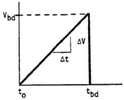
12.2.1 Method A, Rapid Test Method—As shown in Figure 1, a uniform voltage is applied to the test electrode at a certain boost rate from zero to breakdown. The quick test method will be used unless otherwise stated.
12.2.1.1 When determining the supercharging speed, in order to include the speed increase in the new specified value, for a given test sample, the speed of the breakdown will occur within 10 to 20 seconds. In some cases, it is necessary to perform 1 to 2 pre-tests to determine the speed increase. For most materials, a speed increase of 500V/s is used.
12.2.1.2 If the document refers to the growth rate specified by this test method, then even if the breakdown time occasionally appears outside the range of 10 to 20 s, it should continue to be used. If this happens, the number of failures should be recorded in the report.
rate
(V/s) ±20%
100
200
500
1000
2000
5000
Figure 1 Fast test method voltage diagram
12.2.1.3 If a series of tests are to be performed to compare different materials, the same growth rate should be used, keeping the average time between 10 and 20 s. If the breakdown time cannot be maintained within this range, it should be stated in the report.
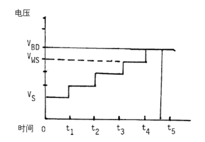
12.2.2 Method B, Step-by-Step Test - Apply a suitable starting voltage to the test electrode and gradually increase the voltage as shown in Figure 2 until a breakdown occurs.
12.2.2.1 From the table listed in Figure 2, the starting voltage Vs can be chosen. In the fast test, this voltage should be close to 50% of the test or expected breakdown voltage.
12.2.2.2 If the starting voltage is lower than the voltage listed in Figure 2, it is recommended to use 10% of the starting voltage as the step-by-step voltage.
12.2.2.3 In the absence of the voltage peaks specified in 6.1.3, the starting voltage shall rise from zero as soon as possible. The same requirements apply to the increase in voltage between adjacent steps. After the initial step is completed, the time required to raise the voltage to the adjacent step should be counted in the time of the adjacent step.
12.2.2.4 If a breakdown occurs during the process of raising the voltage to the next step, the test sample has a withstand voltage Vws which should be equal to the voltage of the completed step. If the breakdown occurs before the end of any step duration, the withstand voltage Vws of the test sample is calculated as the voltage of the last completed step. The breakdown voltage Vbd is used to calculate the dielectric strength. The dielectric strength is calculated from the thickness and the withstand voltage Vws. (See Figure 2)
12.2.2.5 requires 4 breakdowns in 10 steps over a period of 120 s. If there are multiple test samples in a group with fewer than 3 times of breakdown, or if the time is less than 120s, the initial pressure should be reduced and retested. If no breakdown occurs before step 12 or after 720 s, the starting voltage should be increased.
12.2.2.6 Record the starting voltage, the number of steps to increase the voltage, the breakdown voltage and the length of time the breakdown voltage lasts. If the failure occurs when the voltage has just increased to the starting voltage, the dead time is zero.
12.2.2.7 Other time lengths relating to the number of voltage steps shall be stated for the purpose of the test. It is usually used for a length of 20s to 300s (5 minutes). For research, it is necessary in some cases to test a given material for a length greater than the normal length of time.
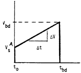
12.2.3 Method C, Slow Test - Apply a starting voltage to the test electrode and increase the voltage as shown in Figure 3 until a breakdown occurs.
12.2.3.1 Select the starting voltage from the slow test specified in 12.2.1. The starting voltage chosen should meet the requirements of 12.2.2.3.
12.2.3.2 Increase the voltage at a certain voltage increase rate starting from the starting voltage specified in the document relating to this test method. In general, the selected rate of increase should be similar to the average rate of increase in the step-by-step test.
12.2.3.3 If a group of multiple test samples breaks down within less than 120 s, then the starting voltage should be reduced or the growth rate should be reduced, or reduced at the same time.
12.2.3.4 If there are multiple test samples in a group with a breakdown voltage less than 1.5 times the initial voltage, the starting voltage should be reduced. If breakdown occurs at a voltage greater than 2.5 times the initial voltage (and after 120 s), the breakdown voltage should increase and the starting voltage should be increased.
A suitable starting voltage, Vs is 0.25, 0.50, 1, 2, 5, 10, 20, 50 and 100 kV, respectively.
Step voltage
in case
Vs(kV)A is
increments
(kV)
Less than 5
Greater than 5 is less than 10
Greater than 10 is less than 25
Greater than 25 is less than 50
Greater than 50 less than 100
Greater than 100
10% of Vs
0.50
1
2
5
10
AVs = 0.5 (Vbd for slow test) unless the parameters specified by the system are not met.
System specified parameters
(t1-t0)=(t2-t1)=...=(60±5)s
Alternate step time. (20±3)s and (300±10)s
120s ≤ tbd ≤ 720s, 60 seconds per step
Figure 2 Step-by-step test voltage diagram
Growth rate (V/s) ± 20%
System specified parameters
1
Tbd>120s
2
5
10
Vbd=>1.5Vs
12.5
20
25
50
100
Figure 3 Schematic diagram of slow test voltage
ASTM D149-2009 dielectric breakdown voltage test method
12.3 Standards for breakdown - dielectric failure or breakdown (as defined in the D1711 terminology) includes increased conductance to limit the maintenance of the electric field. In the test, the phenomenon can be clearly judged by visual inspection and breaking sound across the thickness of the test sample. Test samples were observed to be broken down and broken down in the breakdown area. Such breakdowns are usually an irreversible process. Repetitive voltages can sometimes cause breakdown at low voltages (sometimes below measurable values) and other damage in the breakdown area. This type of reusable voltage often leads to positive evidence of breakdown, which makes the path of breakdown more visible.
12.3.1 In some cases, a rapid increase in leakage current will cause the voltage source to trip without leaving any visible damage on the test sample. This type of failure, usually associated with slow testing at high temperatures, can cause reversible results, and if the test sample is cooled to its initial test temperature before reapplying the voltage, the dielectric strength can be restored. For such failures, the voltage source will be disconnected at relatively low current conditions.
12.3.2在æŸäº›åœºåˆï¼Œç”±äºŽé—ªç»œï¼Œå±€éƒ¨æ”¾ç”µï¼Œé«˜ç”µå®¹æµ‹è¯•æ ·ä¸çš„æ— åŠŸç”µæµæˆ–是æ–è·¯å™¨çš„æ•…éšœé—®é¢˜éƒ½ä¼šé€ æˆç”µåŽ‹æºçš„æ–开。测试ä¸çš„æ¤ç±»é—´æ–ä¸ä¼šé€ æˆå‡»ç©¿ï¼ˆé™¤äº†é—ªç»œæµ‹è¯•å¤–),而å‘生æ¤ç±»é—´æ–的测试也ä¸èƒ½è§†ä¸ºæ»¡æ„的测试。
12.3.3如果æ–路器设置的电æµå¤ªé«˜ï¼Œæˆ–是如果æ–路器的故障å˜åœ¨é—®é¢˜ï¼Œå°†ä¼šé€ æˆæµ‹è¯•æ ·çš„过度燃烧。
12.4测试的数é‡â€”—对于特定æ料,除éžå¦æœ‰è¯´æ˜Žï¼Œå¦åˆ™åº”进行5次击穿。
ASTM D149-2009介电击穿电压试验方法
è€ç”µåŽ‹å‡»ç©¿è¯•éªŒä»ª
13. 计算
13.1对于æ¯æ¬¡æµ‹è¯•è€Œè¨€ï¼Œå‡»ç©¿æ—¶çš„ç»ç¼˜å¼ºåº¦åº”以kV/mm或V/mil为å•ä½æ¥è®¡ç®—,对于é€æ¥æµ‹è¯•è€Œè¨€ï¼Œæ¢¯åº¦åº”以未å‘生击穿的最高电压æ¥éª¤æ¥è®¡ç®—。
13.2计算平å‡ç»ç¼˜å¼ºåº¦åŠæ ‡å‡†å差,或其他å˜é‡çš„测é‡å€¼
è€ç”µåŽ‹å‡»ç©¿è¯•éªŒä»ª14. 报告
14.1报告应包å«ä»¥ä¸‹ä¿¡æ¯ï¼š
14.1.1æµ‹è¯•æ ·çš„é‰´å®šã€‚
14.1.2对æ¯ä¸€ä¸ªæµ‹è¯•æ ·ï¼›
14.1.2.1所测é‡çš„厚度,
14.1.2.2能承å—的最大电压(对é€æ¥æµ‹è¯•è€Œè¨€ï¼‰ï¼Œ
14.1.2.3击穿电压,
14.1.2.4ç»ç¼˜å¼ºåº¦ï¼ˆå¯¹é€æ¥æµ‹è¯•è€Œè¨€ï¼‰ï¼Œ
14.1.2.5击穿强度,åŠ
14.1.2.6击穿的部ä½ï¼ˆç”µæžçš„ä¸å¿ƒï¼Œè¾¹ç¼˜æˆ–外部)。
14.1.3对于æ¯ä¸ªæ ·å“:
14.1.3.1å¹³å‡ç”µä»‹è´¨æ‰¿å—强度(仅对é€æ¥æµ‹è¯•æµ‹è¯•æ ·ï¼‰ï¼Œ
14.1.3.2å¹³å‡ç”µä»‹è´¨å‡»ç©¿å¼ºåº¦ï¼Œ
14.1.3.3å˜é‡çš„è¯´æ˜Žï¼Œæœ€å¥½æ˜¯æ ‡å‡†å差和å˜åŒ–系数。
14.1.3.4æµ‹è¯•æ ·çš„è¯´æ˜Žï¼Œ
14.1.3.5è°ƒèŠ‚å’Œæµ‹è¯•æ ·çš„å‡†å¤‡ï¼Œ
14.1.3.6环境的温度和相对湿度,
14.1.3.7环境介质,
14.1.3.8测试温度,
14.1.3.9电æžçš„说明,
14.1.3.10电压应用的方法,
14.1.3.11如果指定,电æµæ„Ÿåº”å…ƒä»¶çš„å¤±æ•ˆæ ‡å‡†ï¼ŒåŠ
14.1.3.12测试的日期。
ASTM D149-2009介电击穿电压试验方法
è€ç”µåŽ‹å‡»ç©¿è¯•éªŒä»ª
15. 精度和åå·®
15.1表2总结了四个实验室和八ç§ææ–™å®žéªŒå®¤é—´ç ”ç©¶çš„ç»“æžœã€‚è¯¥ç ”ç©¶é‡‡ç”¨åŒä¸€ç”µæžä½“系和åŒä¸€æµ‹è¯•ä»‹è´¨ã€‚9
15.2å•ä¸€æ“ä½œå‘˜ç²¾åº¦â€”â€”æ ¹æ®æµ‹è¯•ææ–™ï¼Œè¯•æ ·åŽšåº¦ï¼Œç”µåŽ‹ä¾›ç»™æ–¹å¼ä»¥åŠæŽ§åˆ¶æˆ–抑制瞬间电压脉冲的æžé™ï¼Œå˜åŒ–å¸¸æ•°ï¼ˆæ ‡å‡†å·®é™¤ä»¥å¹³å‡å€¼ï¼‰åœ¨1%到20%之间å˜åŒ–。如果就åŒä¸€æ ·å“çš„äº”ä¸ªæµ‹è¯•æ ·è¿›è¡Œé‡å¤è¯•éªŒï¼Œå˜åŒ–常数通常ä¸å¤§äºŽ9%。
表2 从四个试验室总结出的ç»ç¼˜å¼ºåº¦æ•°æ®A
ææ–™
å义厚度
(in.)
ç»ç¼˜å¼ºåº¦ï¼ˆV/mil)
æ ‡å‡†åå·®
å˜åŒ–常数(%)
å¹³å‡å€¼
最大值
最å°å€¼
èšå¯¹è‹¯äºŒç”²é…¸ä¹™äºŒé…¯
0.001
4606
5330
4100
332
7.2
èšå¯¹è‹¯äºŒç”²é…¸ä¹™äºŒé…¯
0.01
1558
1888
1169
196
12.6
èšæ°Ÿä¹™çƒ¯ä¸™çƒ¯
0.003
3276
3769
2167
333
10.2
èšæ°Ÿä¹™çƒ¯ä¸™çƒ¯
0.005
2530
3040
2140
231
9.1
PETPçº¤ç»´å¢žå¼ºçŽ¯æ°§æ ‘è„‚
0.025
956
1071
783
89
9.3
PETPçº¤ç»´å¢žå¼ºçŽ¯æ°§æ ‘è„‚
0.060
583
643
494
46
7.9
çŽ¯æ°§æ ‘è„‚çŽ»ç’ƒé’¢
0.065
567
635
489
43
7.6
交è”èšä¹™çƒ¯
0.044
861
948
729
48
5.6
å¹³å‡
8.7
Aæµ‹è¯•æ ·åœ¨æ²¹ä¸ç”¨2型电æžè¿›è¡Œæµ‹è¯•ï¼ˆå‚è§è¡¨1)。
15.3多实验室精度——在ä¸åŒå®žéªŒå®¤ä¸ï¼ˆæˆ–者åŒä¸€å®žéªŒå®¤ä¸åŒè®¾å¤‡ä¸Šï¼‰è¿›è¡Œæµ‹è¯•çš„精度是å˜åŒ–的。通过使用åŒä¸€ç±»åž‹çš„è®¾å¤‡ï¼Œä¸¥æ ¼æŽ§åˆ¶æµ‹è¯•æ ·çš„å‡†å¤‡ï¼Œç”µæžä»¥åŠæµ‹è¯•æµç¨‹ï¼Œå•ä¸ªæ“作员的精度是近似的。但如果对æ¥è‡ªä¸åŒå®žéªŒå®¤çš„结果进行比较,就必须评估ä¸åŒå®žéªŒå®¤çš„精度。
9支撑数æ®å·²ç»å½’档在ASTM国际总部ä¸ï¼Œé€šè¿‡ç”³è¯·ç ”究报告RR:D09-1026å¯èŽ·å¾—这些数æ®ã€‚
15.4如果测试ææ–™ï¼Œè¯•æ ·åŽšåº¦ï¼Œç”µæžç»“构,或环境介质ä¸åŒäºŽè¡¨1所列,或是测试设备ä¸ç”µæµæ„Ÿåº”å…ƒä»¶çš„å‡»ç©¿æ ‡å‡†å¾—ä¸åˆ°ä¸¥æ ¼æŽ§åˆ¶ï¼Œé‚£ä¹ˆå°†æ— 法达到15.2å’Œ15.3ä¸æ‰€è§„定的精度,对于需è¦æµ‹è¯•çš„ææ–™æ¥è¯´ï¼Œæ¶‰åŠæœ¬æµ‹è¯•æ–¹æ³•çš„æ ‡å‡†åº”èƒ½ç¡®å®šè¯¥æ料的精度适用范围。å‚è§5.4~5.8以åŠ6.1.6。
15.5使用特殊的技术和设备ã€ä½¿æ料厚度的精度达到0.01in甚至更å°ã€‚电æžä¸èƒ½æŸåè¯•æ ·çš„æŽ¥è§¦é¢ã€‚准确的测定击穿电压。
15.6å差——该测试方法ä¸èƒ½æµ‹å®šå›ºæœ‰ç»ç¼˜å¼ºåº¦ã€‚测试结果å–å†³äºŽè¯•æ ·çš„å‡ ä½•å½¢çŠ¶ï¼Œç”µæžå’Œå…¶ä»–å¯å˜å‚数,以åŠæ ·å“的性质,这使得很难æè¿°å差。
è€ç”µåŽ‹å‡»ç©¿è¯•éªŒä»ª
16. 关键è¯
16.1å‡»ç©¿ï¼Œå‡»ç©¿ç”µåŽ‹ï¼Œæ ¡å‡†ï¼Œå‡»ç©¿æ ‡æ·®ï¼Œä»‹ç”µå‡»ç©¿ç”µåŽ‹ï¼Œä»‹ç”µå¤±æ•ˆï¼Œä»‹ç”µå¼ºåº¦ï¼Œç”µæžï¼Œé—ªç»œï¼Œç”µæºé¢‘率,过程控制测试,验è¯æµ‹è¯•ï¼Œè´¨é‡æŽ§åˆ¶æµ‹è¯•ï¼Œå¿«é€Ÿå¢žåŠ ï¼Œç ”ç©¶æµ‹è¯•ï¼Œå–æ ·ï¼Œæ…¢é€Ÿï¼Œé€æ¥ï¼ŒçŽ¯å¢ƒä»‹è´¨ï¼Œè€åŽ‹ã€‚
附录
(éžå¼ºåˆ¶ä¿¡æ¯ï¼‰
Xl. ç»ç¼˜å¼ºåº¦æµ‹è¯•çš„æ„义
X1.1 介ç»
Xl.1.1简è¦å›žé¡¾äº†å‡»ç©¿çš„三ç§å‡å®šæœºåˆ¶ï¼Œåˆ†åˆ«æ˜¯ï¼šï¼ˆ1)放电或电晕机制,(2)çƒæœºåˆ¶ï¼Œä»¥åŠï¼ˆ3)固有机制,讨论了在原ç†ä¸Šå¯¹å®žé™…电介质产生影å“çš„å› ç´ ï¼Œå¹¶å¯¹æ•°æ®çš„解释æ供帮助。击穿机制常常与其他机制相结åˆï¼Œè€Œéžå•ç‹¬å‘挥效用。éšåŽçš„讨论仅针对固体和åŠå›ºä½“æ料。
Xl.2 介电击穿的å‡å®šæœºåˆ¶
X1.2.1ç”±æ”¾ç”µé€ æˆçš„击穿——在对工业æ料进行的许多测试ä¸ï¼Œéƒ½æ˜¯ç”±äºŽæ”¾ç”µé€ æˆäº†å‡»ç©¿ï¼Œè¿™é€šå¸¸é€ æˆè¾ƒé«˜çš„局部场。对于固体ææ–™æ¥è¯´ï¼Œæ”¾ç”µå¸¸å¸¸å‘生在环境介质ä¸ï¼Œå› æ¤å¢žåŠ 测试的区域将在电æžè¾¹ç¼˜ä¸Šæˆ–外侧产生击穿。放电也会å‘生在内部出现或生æˆçš„ä¸€äº›æ³¡æ²«æˆ–æ°”æ³¡é‡Œã€‚è¿™ä¼šé€ æˆå±€éƒ¨çš„侵蚀或化å¦åˆ†è§£ã€‚这些过程将一直æŒç»åˆ°åœ¨ç”µæžé—´å½¢æˆå®Œå…¨çš„失效通路为æ¢ã€‚
X1.2.2çƒå‡»ç©¿â€”—在置于高强度电场时,在许多æ料内的局部路径上会积èšå¤§é‡çš„çƒï¼Œè¿™å°†é€ æˆç”µä»‹è´¨å’Œç¦»å导电性能的æŸå¤±ï¼Œè¿›è€Œè¿…速产生çƒé‡ï¼Œæ‰€äº§ç”Ÿçš„çƒé‡å°†å¤§äºŽæ‰€èƒ½è€—散掉的çƒé‡ã€‚由于æ料的çƒä¸ç¨³å®šæ€§ï¼Œå¯¼è‡´äº†å‡»ç©¿çš„å‘生。
X1.2.3固有击穿——如果放电或çƒç¨³å®šæ€§éƒ½ä¸èƒ½é€ æˆå‡»ç©¿ï¼Œé‚£ä¹ˆåœ¨ç”µåœºå¼ºåº¦å¤§åˆ°è¶³ä»¥åŠ 速电å穿过æ料时,ä»å°†å‘ç”Ÿå‡»ç©¿ã€‚æ ‡å‡†ç”µåœºå¼ºåº¦è¢«ç§°ä¸ºå›ºæœ‰ç»ç¼˜å¼ºåº¦ã€‚虽然机制本身也许已ç»æ¶‰åŠï¼Œä½†æœ¬æµ‹è¯•æ³•ä»ä¸èƒ½æµ‹è¯•å›ºæœ‰ç»ç¼˜å¼ºåº¦ã€‚
Xl.3 ç»ç¼˜æ料的性质
X1.3.1固æ€å·¥ä¸šç»ç¼˜æ料通常是éžå‡åŒ€çš„,且å«æœ‰è®¸å¤šä¸åŒçš„ç”µä»‹è´¨ç¼ºé™·ã€‚è¯•æ ·ä¸Šå¸¸å¸¸å‘生击穿的区域,并ä¸æ˜¯é‚£äº›ç”µåœºå¼ºåº¦æœ€å¤§çš„区域,有时甚至是那些远离电æžçš„区域。在应力下å·ä¸çš„薄弱环节有时将决定测试的结果。
X1.4 æµ‹è¯•å’Œæµ‹è¯•æ ·çŠ¶å†µçš„å½±å“å› ç´
X1.4.1电æžâ€”—通常,éšç€ç”µæžåŒºåŸŸçš„å¢žåŠ ï¼Œå‡»ç©¿ç”µåŽ‹ä¼šé™ä½Žï¼Œè¿™ç§å½±å“å¯¹äºŽè–„è¯•æ ·æ¥è¯´æ›´ä¸ºæ˜Žæ˜¾ã€‚电æžçš„å‡ ä½•å½¢çŠ¶ä¹Ÿä¼šå½±å“测试的结果。制作电æžçš„æ料也会对测试结果产生影å“ï¼Œè¿™æ˜¯å› ä¸ºç”µæžæ料的çƒå¯¼æ€§å’ŒåŠŸå‡½ä¼šå¯¹çƒæœºåˆ¶å’Œå‘电机制产生影å“。通常æ¥è¯´ï¼Œç”±äºŽç¼ºä¹ç›¸å…³çš„实验数æ®ï¼Œæ‰€ä»¥å¾ˆéš¾ç¡®å®šç”µæžæ料的影å“。
X1.4.2è¯•æ ·åŽšåº¦â€”â€”å›ºä½“å·¥ä¸šç»ç¼˜æ料的ç»ç¼˜å¼ºåº¦ä¸»è¦å–å†³äºŽè¯•æ ·çš„åŽšåº¦ã€‚ç»éªŒæ˜¾ç¤ºï¼Œå¯¹äºŽå›ºä½“å’ŒåŠå›ºä½“ææ–™æ¥è¯´ï¼Œç»ç¼˜å¼ºåº¦ä¸Žä»¥è¯•æ ·åŽšåº¦ä¸ºåˆ†æ¯çš„分数æˆå比,更多的è¯æ®æ˜¾ç¤ºï¼Œå¯¹äºŽç›¸å¯¹å‡åŒ€çš„固体æ¥è¯´ï¼Œç»ç¼˜å¼ºåº¦ä¸ŽåŽšåº¦çš„å¹³æ–¹æ ¹äº’ä¸ºå€’æ•°ã€‚å¦‚æžœå›ºä½“è¯•æ ·èƒ½ç†”åŒ–åŽå€’入到固定电æžä¹‹é—´å¹¶å‡å›ºä¸‹æ¥ï¼Œé‚£ä¹ˆç”µæžé—´è·çš„å½±å“å°†å¾ˆéš¾å¾—åˆ°æ˜Žç¡®çš„å®šä¹‰ã€‚å› ä¸ºåœ¨è¿™ç§æƒ…况下,å¯ä»¥éšæ„固定电æžé—´è·ï¼Œæ‰€ä»¥ä¹ 惯在液体或å¯æº¶å›ºä½“ä¸è¿›è¡Œç»ç¼˜å¼ºåº¦æµ‹è¯•ï¼Œæ¤æ—¶ç”µæžé—´å…·æœ‰æ ‡å‡†çš„å›ºå®šç©ºé—´ã€‚å› ä¸ºç»ç¼˜å¼ºåº¦å–决于厚度,所以如果在报告ç»ç¼˜å¼ºåº¦æ•°æ®æ—¶ç¼ºä¹æµ‹è¯•æ‰€ç”¨è¯•æ ·çš„èµ·å§‹åŽšåº¦ï¼Œé‚£ä¹ˆè¿™æ ·çš„æ•°æ®å°†æ¯«æ— æ„义。
X1.4.3æ¸©åº¦â€”â€”è¯•æ ·å’ŒçŽ¯å¢ƒä»‹è´¨çš„æ¸©åº¦å°†å½±å“ç»ç¼˜å¼ºåº¦ï¼Œè™½ç„¶å¯¹äºŽå¤§å¤šæ•°ææ–™æ¥è¯´ï¼Œå¾®å°çš„环境温度å˜åŒ–对ææ–™é€ æˆå½±å“å¯ä»¥å¿½ç•¥ä¸è®¡ã€‚通常,ç»ç¼˜å¼ºåº¦éšæ¸©åº¦çš„å‡é«˜è€Œé™ä½Žï¼Œä½†å…¶å¼ºåº¦çš„æžé™å–决于被测æ料。众所周知,由于æ料需è¦å®¤æ¸©ä»¥å¤–çš„æ¡ä»¶ä¸‹å‘挥作用,所以有必è¦åœ¨æ¯”期望æ“作温度更大的范围里,对ç»ç¼˜å¼ºåº¦ä¸Žæ¸©åº¦çš„关系进行确定。
X1.4.4时间——电压应用的速率也会影å“测试结果。通常,击穿电压éšç”µåŽ‹åº”ç”¨é€ŸçŽ‡çš„å¢žåŠ è€Œæ高。这是预料之ä¸çš„ï¼Œå› ä¸ºçƒå‡»ç©¿æœºåˆ¶æœ‰èµ–于时间,而放电机制也有赖于时间,虽然在一些情况下,åŽä¸€ç§æœºåˆ¶é€šè¿‡äº§ç”Ÿå±€éƒ¨ç”µåœºé«˜ä¸´ç•Œå¼ºåº¦é€ æˆå¿«é€Ÿå¤±æ•ˆã€‚
X1.4.5波形——通常,应用电压的波形也会影å“ç»ç¼˜å¼ºåº¦ã€‚在本测试方法的é™åˆ¶è¯´æ˜Žä¸ï¼Œæ³¢å½¢çš„å½±å“是ä¸æ˜¾è‘—的。
X1.4.6频率——对于本测试法,在工业用电频率范围内,频率的å˜åŒ–对ç»ç¼˜å¼ºåº¦çš„å½±å“å°†ä¸æ˜¯é‚£ä¹ˆæ˜¾è‘—。但是,ä¸èƒ½ä»Žæœ¬æµ‹è¯•æ³•æ‰€å¾—结果ä¸æŽ¨æ–出其他éžå·¥ä¸šç”¨ç”µé¢‘率(50到60HHz)对ç»ç¼˜å¼ºåº¦çš„å½±å“。
X1.4.7环境介质——通常测试具有高击穿电压的固体ç»ç¼˜ææ–™ï¼Œæ˜¯å°†è¯•æ ·æµ¸å…¥åˆ°æ¶²ä½“ä»‹è´¨ä¸ï¼Œä¾‹å¦‚å˜åŽ‹å™¨æ²¹ï¼Œç¡…油,或是氟利昂ä¸ï¼Œä»¥å‡å°å‡»ç©¿å‰è¡¨é¢æ”¾ç”µçš„å½±å“。这已ç»ç”±S.Whitehead10所æ示,为了é¿å…å›ºä½“è¯•æ ·åœ¨è¾¾åˆ°å‡»ç©¿ç”µåŽ‹å‰åœ¨çŽ¯å¢ƒä»‹è´¨ä¸å‘生放电现象,在交æµç”µæµ‹è¯•ä¸ï¼Œæœ‰å¿…è¦ç¡®ä¿ï¼š
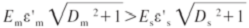 (X1.1)
如果浸入的液体介质是一ç§ä½ŽæŸè€—æ料,该公å¼å¯ä»¥ç®€åŒ–为:
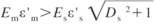 (X1.2)
如果浸入的液体介质是一ç§åŠå¯¼ä½“æ料,那么该公å¼å¯ä»¥å˜ä¸ºï¼š
 (X1.3)
å¼ä¸ï¼š
E=ç»ç¼˜å¼ºåº¦ï¼›
f=频率;
ε和ε′=介电常数;
D=è€—æ•£å› æ•°ï¼›
o=电导率(S/m);
ä¸‹æ ‡ï¼š
m指浸入介质;
r指相对值;
O指自由空间;
(εO=8.854×10⁻¹²F/m)
s指固体电介质。
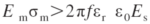
X1.4.7.1Whitehead指出,è¦é¿å…表é¢æ”¾ç”µï¼Œåˆ™åº”æ高Em和εm或是æ高σm。通常规定使用å˜åŽ‹å™¨æ²¹ï¼Œå…¶ä»‹ç”µæ€§èƒ½æ˜¯è¿™æ ·çš„,如果电场强度Es达到以下水平,则会å‘生边缘击穿:
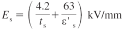 (X1.4)
å¦‚æžœæµ‹è¯•æ ·å¾ˆåŽšï¼Œä¸”å…¶ä»‹ç”µå¸¸æ•°å¾ˆå°ï¼Œé‚£ä¹ˆå«æœ‰tsçš„é‡å°†æˆä¸ºç›¸å¯¹å½±å“å› æ•°ï¼Œä»‹ç”µå¸¸æ•°ä¸Žç”µåœºå¼ºåº¦çš„ä¹˜ç§¯å°†è¿‘ä¼¼äºŽä¸€ä¸ªå¸¸æ•°ã€‚11Whitehead也指出(p. 261)使用潮湿的åŠå¯¼ä½“油将能有效å‡å°‘边缘放电的现象。如果电æžé—´çš„击穿路径仅在固体ä¸å‡ºçŽ°ï¼Œé‚£ä¹ˆæ¤ä»‹è´¨å°†ä¸èƒ½ä¸Žå…¶ä»–介质进行比较。也应该注æ„到如果固体是多å”的或是能够被浸入介质充满,固体的击穿强度将å—到浸入介质电气性质的直接影å“。
X1.4.8相对湿度——相对湿度影å“ç»ç¼˜å¼ºåº¦æ˜¯å› 为测试ææ–™å¸æ”¶çš„水分或表é¢å¸é™„的水分将影å“介质æŸè€—和表é¢ç”µå¯¼çŽ‡ã€‚å› æ¤ï¼Œå®ƒçš„é‡è¦æ€§å¾ˆå¤§ç¨‹åº¦ä¸Šæœ‰èµ–于测试æ料的性质。但是,å³ä½¿ææ–™åªå¸æ”¶äº†ä¸€ç‚¹ç”šè‡³æ²¡æœ‰å¸æ”¶æ°´åˆ†ï¼Œä»ä¼šå—到影å“ï¼Œå› ä¸ºåœ¨æœ‰æ°´çš„æƒ…å†µä¸‹ï¼Œå°†å¤§å¤§æ高放电的化å¦æ•ˆåº”。除æ¤ä¹‹å¤–,还应调查暴露在电场强度ä¸çš„å½±å“ï¼Œé€šå¸¸é€šè¿‡æ ‡å‡†çš„è°ƒèŠ‚æµç¨‹æ¥æŽ§åˆ¶æˆ–é™åˆ¶ç›¸å¯¹æ¹¿åº¦çš„å½±å“。
10文献:Whitehead, S., 固体介电击穿, Oxford University Press, 1951.
X1.5 评估
X1.5.1通电设备ç»ç¼˜çš„一个基本è¦æ±‚就是它应能承å—å¾—ä½åœ¨æœåŠ¡ä¸æ–½åŠ äºŽå®ƒçš„ç”µåŽ‹ã€‚å› æ¤å¾ˆæœ‰å¿…è¦å¯¹æµ‹è¯•è¿›è¡Œè¯„价,以评价处于高压应力æ¡ä»¶ä¸‹çš„æ料性能。介质击穿电压测试是一ç§æµ‹å®šæ料是å¦éœ€è¦è¿›ä¸€æ¥è€ƒå¯Ÿçš„åˆæ¥æµ‹è¯•ï¼Œä½†æ˜¯å®ƒæ— 法就两个é‡è¦æ–¹é¢è¿›è¡Œå…¨éƒ¨è¯„估。首先,安装在设备上的ææ–™æ¡ä»¶ä¸Žæµ‹è¯•æ¡ä»¶å¤§ä¸ºä¸åŒï¼Œå°¤å…¶åœ¨è€ƒè™‘了电场结构和暴露在电场ä¸çš„ææ–™é¢ç§¯ï¼Œç”µæ™•ï¼Œæœºæ¢°åº”力,周围介质以åŠä¸Žå…¶ä»–æ料的连接之åŽï¼Œæ›´æ˜¯å¦‚æ¤ã€‚第二,在æœåŠ¡æ—¶ï¼Œä¼šå‡ºçŽ°å¾ˆå¤šæ¶åŠ£çš„å½±å“,例如çƒï¼Œæœºæ¢°åº”力,电晕åŠå…¶äº§ç‰©ï¼Œæ±¡æŸ“物ç‰ç‰ï¼Œéƒ½ä¼šä½¿å‡»ç©¿ç”µåŽ‹è¿œä½ŽäºŽæœ€åˆå®‰è£…时的击穿电压值。在实验室测试ä¸ï¼Œå¯ä»¥åˆå¹¶å…¶ä¸çš„一些影å“,进而对该ææ–™åšå‡ºæ›´å‡†ç¡®çš„估计,但是最终考察的ä»ç„¶æ˜¯é‚£äº›å¤„于实际æœåŠ¡çš„æ料性质。
X1.5.2介质击穿测试能作为æ料检测或是质é‡æŽ§åˆ¶æµ‹è¯•ï¼Œä½œä¸ºä¸€ç§æŽ¨æµ‹å…¶ä»–æ¡ä»¶çš„手段,例如å˜çŽ‡ï¼Œæˆ–是指明æ¶åŒ–的过程,如çƒè€åŒ–。在使用本测试法时,击穿电压的相对值比ç»å¯¹å€¼æ›´é‡è¦ã€‚
X2. D149测试法所涉åŠçš„æ ‡å‡†
X2.1 介ç»
X2.1.1本附录所æ供的文件目录将涉åŠåˆ°å¤§é‡çš„ASTMæ ‡å‡†ï¼Œè¿™äº›æ ‡å‡†éƒ½ä¸Žåœ¨ç”µæºé¢‘率下电介质强度的测定有关,或与测试设备元件或用于测定该性质的元件有关。虽然我们ç«å°½å…¨åŠ›ï¼ŒåŠ›å›¾å°†æ‰€æœ‰æ¶‰åŠD149æµ‹è¯•æ³•çš„æ ‡å‡†éƒ½åŒ…å«è¿›æ¥ï¼Œä½†æ˜¯è¯¥æ¸…å•ä»æ˜¯ä¸å®Œå…¨çš„,在本附录出版之åŽç¼–å†™æˆ–ä¿®æ”¹çš„æ ‡å‡†éƒ½æœªèƒ½åŒ…å«è¿›æ¥ã€‚
X2.1.2åœ¨ä¸€äº›æ ‡å‡†ä¸ï¼ŒæŒ‡å®šè¦ç”¨D149测试法测定介质强度或击穿电压,但是其å‚考本测试法的方å¼ä¸ä¸€å®šç¬¦åˆ5.5çš„è¦æ±‚。除éžè¯¥æ–‡ä»¶ä¸Ž5.5相一致,å¦åˆ™ä¸ç”¨ä½¿ç”¨å…¶ä»–文件,包括本目录所列的文件,æ¥ä½œä¸ºæœ¬æµ‹è¯•æ³•çš„å‚考。
ASTM D149-2009介电击穿电压试验方法
表X2.1 试验方法D149引用的ASTMæ ‡å‡†
ASTM代å·
å·å·
æ ‡å‡†ç±»åž‹
æ ‡é¢˜
ä¸å…·ä½“到æŸç§æ料或ææ–™ç±»åˆ«çš„é€šç”¨æ ‡å‡†ï¼š
D1389
10.01
测试方法
薄电气ç»ç¼˜æ料,验è¯æµ‹è¯•
D1868
10.01
测试方法
局部放电脉冲的检测和测é‡
D1999
08.02
指导
ä¸ºå›½é™…å•†åŠ¡è€Œå¯¹æµ‹è¯•æ ·å’Œæµ‹è¯•å‚数进行的选择
D2275
10.01
测试方法
表é¢å±€éƒ¨æ”¾ç”µä¸Žç”µåŽ‹è€å—
D2304
10.01
测试方法
çƒè€åŠ›ï¼Œåˆšæ€§ç»ç¼˜ææ–™
D3151
10.02
测试方法
电应力下的çƒå¤±æ•ˆ
D3382
10.02
测试方法
测é‡ç”±äºŽå±€éƒ¨æ”¾ç”µè€Œè½¬ç§»çš„能é‡å’Œç”µè·
D3426
10.02
测试方法
ç»ç¼˜å¼ºåº¦ä½¿ç”¨çš„脉冲波
D3755
10.02
测试方法
ç»ç¼˜å¼ºåº¦æ‰€ä½¿ç”¨çš„ç›´æµç”µåŽ‹
D2756
10.02
测试方法
æ ‘çŠ¶å‡»ç©¿
E1420
12.02
指导
电离è¾å°„æ料的确定
织物ã€çº¤ç»´ã€çº¸å¼ ã€ç£å¸¦ã€è†œã€æŸ”性å¤åˆæ料和涂层织物:
D69
10.01
测试方法
摩擦带
D202
10.01
测试方法
未处ç†çš„ç»ç¼˜çº¸å¼
D295
10.01
测试方法
涂漆棉织带
D373
10.01
specification
黑色斜å‘截切涂漆布和胶带
D619
10.01
测试方法
硫化纤维
D902
dog chew toys,dog puzzle toys,dog toys for large dogs,indestructible dog toys,dog toys for small dogs
Ningbo XISXI E-commerce Co., Ltd , https://www.petspetscare.com